


 Custom services
 English (pdf)
 Article in xml format
 Article references
 Send this article by e-mail
 Cited by SciELO
  Cited by Google
  Similars in
SciELO
Similars in
SciELO  Similars in Google
 Permalink
Introduction
Wright first described atlanto-axial fusion using C2 translaminar screws in 20041. It is considered to be a salvage or alternative technique in those cases were the C2 pedicle does not allow the insertion of screws because of its size or the presence of a high riding vertebral artery. This technique is quite simple, and reduces the risk of medullar or vascular damage with a minimal cervical exposure.
In order to perform this technique with 3.5 mm diameter bicortical screws, a lamina width of at least the same diameter as the screw is needed and also a spinous process high enough to admit two crossing screws (this implies a height of at least 7 mm).
There are published reports using computed tomography or calipers for the description of the lamina of C2 in adults2-20 (Appendix I). A total of forty papers were reviewed and resulted in 805 screws being used, 67 of which had cortical breach. Nevertheless, a study using a submillimeter computed tomography (CT) scan (resolution of less than one millimeter, the most accurate existing method) in a Caucasian population is missing.
Thus, the main objective of this study is to describe the ability of the C2 spinous process to admit two crossing screws in a European population, measuring inner and outer dimensions in the lamina and the spinous process.
Material and methods
This study was performed on 150 Spanish (Caucasian) patients who came to our institution to have a routine cervical CT scan, prospectively collected. The exclusion criteria were age younger than 18 years and occurrence of tumors, infections, trauma or any other condition involving the atlanto-axial segment.
Demographic data (age and sex) were registered. Height and weight were not taken into account because previous studies reported no association between these and vertebral size2. All the patients were adults and, therefore, no changes were expected due to growth.
Submillimeter slices (0.7 mm) every 0.4 mm were done with a 64 multi-detector CT scan (TCMC:64 phased array MDCT, Axiom, Siemens Healthcare, Erlangen, Germany). This type of CT scan has the ability to give an isometric image with the original model, i.e., the reconstruction has the same resolution as the original image. Therefore, it makes it possible to orientate the image on any plane of space for reconstructions from the volume data obtained with the CT scan, and all the measurements can be done without losing isometry. The bone window with high frequency algorithm was used to be more accurate (level 150 HU; width 1500 HU).
The measurements for the lamina were centered on the longest axis of the lamina on the axial plane. Once this plane was determined, sagittal, axial and coronal planes of the lamina were taken, in order to obtain perfect tangential measurements. The measures were taken at the thinnest point of the lamina. On the coronal plane, the width and height at the outer and inner cortical borders were measured (Fig. 1).
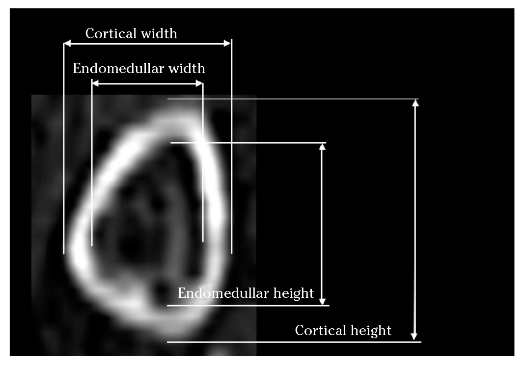
Figure 1. CT scan. Coronal plane showing width and height at the outer and inner cortical borders of the lamina.
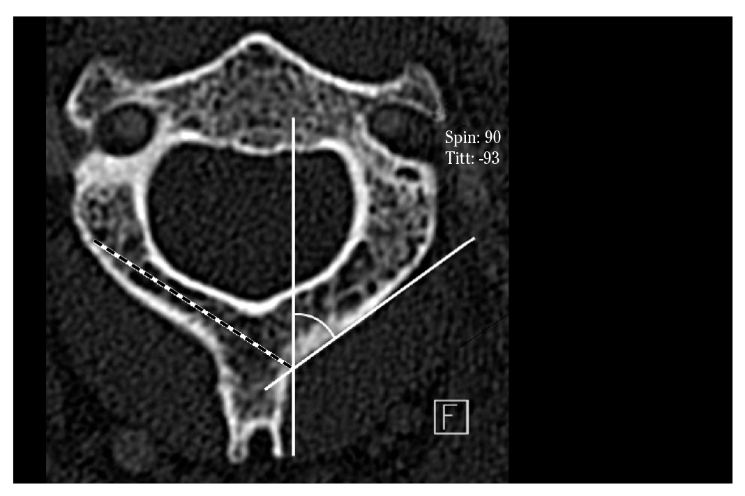
Measurements in the spinous process slices were made along the transverse and longitudinal axis of the spinous process of C2. On the coronal plane, the endomedullar and cortical height of the spinous process and the inclination of the lamina (α SLOP) were measured (Fig. 2). On the axial plane, we measured the endomedullar and cortical length of the spinous process (Fig. 3), the maximal screw length (MSL) and the spinolaminar angle (SLA) (Fig. 4). The axis of the maximal screw length was defined by the inflexion point of the spinolaminar angle and the center of the lamina at its thinnest point. All the measurements were made bilaterally, except those of the spinous process.
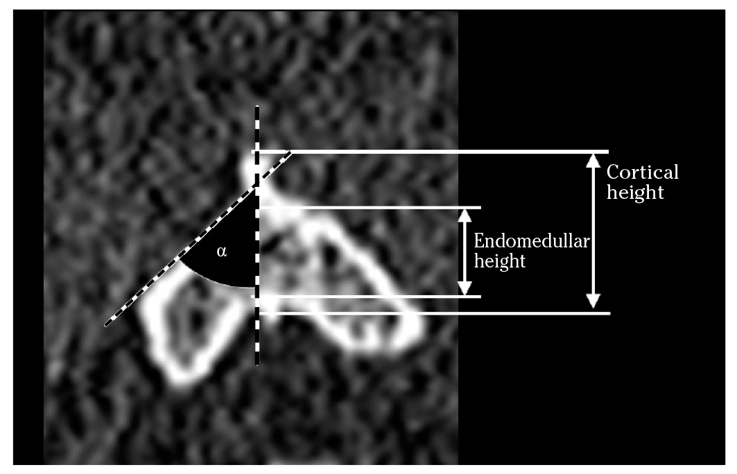
Figure 2. CT scan. Coronal plane. Cortical and endomedullar height of the spinous process. α: inclination angle of the lamina relative to the vertical (SLOP).
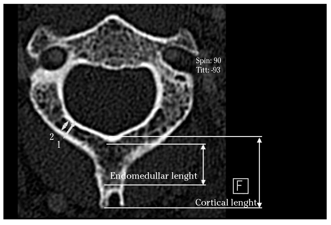
Figure 3. CT Scan. Axial plane showing cortical (1) and endomedullar (2) width of the lamina; cortical and endomedullar lengths of the spinous process were indicated.
In the statistical analyses, the normal distribution of the different variables was double checked, graphically (through visual inspection with the standardized normal probability plot) and numerically (Kolmogorov-Smirnov and Shapiro-Wilk tests). The homogeneity of standard deviation (SD) was also tested using variance-comparison tests. The different morphological measurements were described by mean (SD), and the average values of men and women were compared using Student's t-test for independent samples. Only the cortical height had inequality of variances and therefore a Welch's approximation was used to compare the subgroups' means of this variable.
Potential associations between the cortical and endomedullar height and the cortical and endomedullar height of the C2 spinous process were assessed estimating Pearson's correlation coefficients (r).
Furthermore, potential differences between right/left and cortical/endomedullar measurements were tested using the matched design in a paired t test.
Patients were categorized using as criteria: endomedullar height of 7 mm and endomedullar height of 9 mm.
All p-values presented were 2-tailed, and p <0.05 was considered to be statistically significant. Analyses were performed using STATA/SE version 13.0 (StataCorp LP, College Station, TX, USA).
Results
Of the 150 patients included in the study, 66% were men. Mean age was 58 years (range 25-85, SD= 13), slightly higher in men than in women (59.4, SD= 12.8 vs. 55.6, SD= 14.4; p= 0.1).
The morphological measurements were summarized in table 1. Regarding the measures at the lamina, the mean width of the left cortical lamina was 0.3 mm larger than the right side. On average, the cancellous part of the left lamina was 0.2 mm larger than the right side. No height differences were observed between left and right sides of the cortical and cancellous part.
Table 1. Morphologic measurements of the posterior arch of C2
| Total (n = 150) | Male (n = 99) | Female (n = 51) | p$ | |||||
|---|---|---|---|---|---|---|---|---|
| Mean | SD | Mean | SD | Mean | SD | |||
| Spinous process | ||||||||
| Cortical length | 15.7 | 3.5 | 16.5 | 3.4 | 14.2 | 3.2 | <0.001 | |
| Cortical height | 11.9 | 2.2 | 12.3 | 1.9 | 11.0 | 2.4 | <0.001 | |
| Endomedular length | 12.5 | 3.9 | 13.3 | 3.8 | 10.9 | 3.5 | <0.001 | |
| Endomedular height | 8.4 | 2.1 | 8.9 | 2.0 | 7.4 | 2.0 | <0.001 | |
| Lamina | ||||||||
| Cortical width | Left | 7.2 | 1.5 | 7.3 | 1.5 | 7.0 | 1.3 | 0.254 |
| Right | 6.9 | 1.3 | 7.1 | 1.4 | 6.6 | 1.2 | 0.048 | |
| Cortical height | Left | 13.0 | 1.5 | 13.4 | 1.3 | 12.0 | 1.4 | <0.001 |
| Right | 13.1 | 1.6 | 13.6 | 1.5 | 12.1 | 1.4 | <0.001 | |
| Endomedular width | Left | 4.8 | 1.5 | 5.0 | 1.5 | 4.5 | 1.4 | 0.043 |
| Right | 4.6 | 1.4 | 4.8 | 1.4 | 4.2 | 1.3 | <0.001 | |
| Endomedular height | Left | 9.0 | 1.8 | 9.8 | 1.7 | 8.3 | 1.7 | <0.001 |
| Right | 9.0 | 1.9 | 9.5 | 1.9 | 7.9 | 1.5 | <0.001 | |
| Maximal screw length | ||||||||
| Left | 31.7 | 3.9 | 32.5 | 3.7 | 30.1 | 3.9 | <0.001 | |
| Right | 32.0 | 4.5 | 33.3 | 3.9 | 29.4 | 4.6 | <0.001 | |
| Spinolaminar angle* | ||||||||
| Left | 49.4 | 4.7 | 49.2 | 4.4 | 49.8 | 5.2 | 0.4 | |
| Right | 48.4 | 4.7 | 47.8 | 4.5 | 49.6 | 4.8 | 0.0 | |
| Inclination of the lamina* | ||||||||
| Left | 144.4 | 10.2 | 144.2 | 10.6 | 144.7 | 9.4 | 0.8 | |
| Right | 142.4 | 9.8 | 142.7 | 9.6 | 141.9 | 10.2 | 0.7 | |
All measures in mm except *in degrees; $: Student's t-test for independent samples.
On average, the length and height of the spinous process were respectively 3.2 and 3.5 mm longer in the cortical part than in the cancellous part. The mean spinolaminar angle was 49º (SD= 5), the maximum screw length 3.18 (SD= 0.4) cm. and the SLOP angle 143º (SD= 10).
Although not much variability was observed in measurements between patients, differences between men and women were statistically significant for almost all the measurements.
Overall, differences lower than 0.3 mm between the right and left measurements were found, despite being statistically significant. Likewise, statistically significant differences between the cortical and endomedullar measurements ranged from 2.3 to 4.1 mm. Statistically significant positive associations between the cortical and endomedullar measurements were also found (r ranging from 0.73 to 0.95).
Finally, we observed that the height of the spinous process was smaller than 7 mm in 24% of the patients and smaller than 9 mm in 60% of them.
Discussion
Posterior upper cervical fixation has been developed in recent decades. The potential risk of damage to the vertebral artery and violation of the medullar canal has led spinal surgeons to develop new options of fixation.
Several morphometric studies have investigated the feasibility of the lamina and the spinous process of C2 to admit two crossing screws; many of these studies focused on the size of the lamina, which is a limiting factor for this technique 2-19. Nor should we forget the dimensions of the spinous process as a second limiting factor. The first screw is easy to insert but the second one is more challenging1,20,21. We also decided to assess the spinolaminar junction and spinous process in order to clarify this problem.
With laminar screws the risk of injury to the vertebral artery has been controlled, depending on the length of the screw14, but not the risk of neurologic injury due to the drill or the screw breaking through the inner cortex of the lamina4,11,22,23.
Most of the morphological studies have used CT scans, both in specimens and patients. Ma et al reported that a laminar thickness of at least 4 mm is acceptable to insert a translaminar screw; 83.3% of their sample fulfilled this condition, 5% had a smaller lamina and 9.2% could accept only one screw10.
It is common to have a patient with a laminar width of 5 mm in whom we have to insert a 3.5 mm screw1,20,21. Four studies have assessed the endomedullar dimensions of C2, not including the lamina4,6,14,18 (Appendix I). The variability in the results underlines that no assumption can be made regarding the dimensions of C2.
Our study is accurate for measuring intramedullary size as we can choose the thinnest part of the lamina by CT scan in humans. Others authors used calipers to make gross measurements, which would correspond to our cortical measurements3,4,8,10,13,19. We think that measuring the inner diameter is more appropriate as the screw will be inserted inside the inner part -between both cortices- and the threads will sink into the cortical.
The facts that the differences between the cortical and endomedullar measurements ranged from 2.3 to 4.1 mm, and the correlation between the cortical and endomedullar measurements ranged from 0.73 to 0.95 mm, imply that the outer dimensions grossly overestimate the endomedullar dimensions, and that some of them are unsafely correlated. The outer dimensions are useless for surgical planning. We observed that the differences are greater in height than in width; this means that the cortical thickness is greater in the upper and lower borders than in the internal and external surfaces.
Technically, the entry point for screws is at the base of the spinous process of C2. The first screw should be inserted close to the cranial edge and the second screw should be placed close to the caudal edge, in order to avoid intersection of the trajectories of the screws. It is preferable to have a dorsal cortical breach, rather than a ventral breach. In fact, some authors have used bicortical laminar fixation24. This should dictate the orientation of the screw25. Nagata et al have studied the way of placing a single screw horizontally in the spinous process in cases of thin C2 lamina26. Others inserted the translaminar screws ipsilaterally in cases of compromise with the spinous process27.
The dimensions of the screws make it necessary to have a minimum spinous process endomedullar height of 7 mm (to accept two 3.5 mm screws). Ma et al considered that surgeons need 2 mm more to insert the screw, thus a spinous process height of at least 9 mm would be required. In their study only three specimens were not suitable for the crossing screw technique10.
In our study, the endomedullar spinous process height was less than 7 mm in 24% of the patients. This means that one fourth of our population would not be suitable for this technique. Further, only 40% of the patients have a height of more than 9 mm. Sixty percent of the patients would pose difficulties for the positioning of the screws, which would not be easy or possible. In those patients with a spinous process height of more than 7 mm but less than 9 mm, (36% of the sample), the surgeon should be especially careful when placing the first screw because any variation on the insertion point would not allow insertion of the second screw. Our data show that the thickness of the midportion of the lamina is the key factor that determines the feasibility of safe screw placement.
The fact that our adult sample is Spanish (Caucasian) may be a limitation to generalizing the findings of this study but it may be a useful orientation when dealing with Caucasian patients.
In conclusion, there is a relevant variability in the sizes of the lamina and spinous process of C2 in the Spanish population. Our results show that 24% would not be candidates for having the crossing screw technique in the spinous process of C2, and only 40% have a height suitable for placing the screws comfortably. There was no correlation between the size of the lamina and the age of the patient. The prevalence of the population who were not suitable for even a single screw was 26.7% and up to 43% of the patients were not suitable for two crossing screws in the spinous process. It is therefore mandatory to measure the dimensions of the posterior arch of C2 with CT to avoid risk of screw malposition. This study will provide information about the size of the vertebra to be instrumented and also the ideal entry point on each side, having the spinous process as a reference to place the screws.

